If you've just picked up a set of trumpet horns for your 1963-65
Riviera or 1964-65 full-size Buick, you may find that they don't work
real well (if at all). The horns frequently suffer from
accumulated corrosion inside, which impairs their ability to operate
as intended. The fix is a complete rebuild. The procedure is
described below. Information about the wiring
harness is at the bottom of the page.
|
||||||||||||||||||||||||||||||||||||
 Horn
identification:
Horn
identification:| Small horn | Large horn | |||||
| length | pitch | stamp* | length | pitch | stamp* | |
| 1963 | 14" | Bb | 948 | 24" | C | 949 |
| 1964 | 12" | C | 898 | 22" | D | 897 |
| 1965 | N/A | B | 930** | 22" | D | 897 |
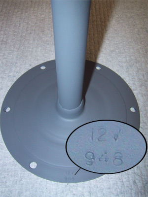
* There are identifying numbers stamped into the flange of the trumpet base. These numbers correspond with the last 3 digits of the GM part number (group 2.810, part number 1999xxx).
** The 1965 small horn was superceded with the same small horn that was used in 1964.
Horn rebuild:
The first step is to disassemble the horns. The actuator and the trumpet are attached with pop rivets. You have to drill these out. Use a 3/16", 13/64", or 7/32" bit. Drill out enough meat to get to the level of the mounting flange, then knock the rivet out with a punch.
After the horns are apart, you'll probably find that the diaphragms are covered with rust and scale. This is the root of the problem, as it prevents the diaphragm from vibrating properly. There may be rust inside the actuator and on trumpet mounting flange as well. This has to come off. Look here for some tips on effective rust removal. If you have severe damage to either the diaphragm or the actuator, they may not work even after they have been cleaned up. These parts are the same in all large diameter GM horns of the era; the only unique part is the trumpet itself.. Find some cheap donor horns (they're stamped Delco Type-S) and cannibalize them.
Now that the old paint and rust have been removed (notice how I gloss over that part), you need to a) perform a little routine maintenance, b) do what you can to prevent a reoccurrence, and c) reassemble the horns:
The only maintenance is to clean the points. I first pried the points apart by inserting a screwdriver and gently twisting, then I slipped a piece of emery cloth between the contacts and pulled it across. Be sure to do this for both the upper and lower contacts.
To limit the likelihood of rust forming in the future, I painted the horns with a rust-inhibiting primer. I painted all of the trumpet (the horns and both sides of the mounting flange), both sides of the diaphragm, and the outside of the actuator and the mounting flange. I chose not to paint the actuator circuitry so as not to interfere with the points or the solenoid. I also made new gaskets to keep moisture from entering between trumpet and the actuator shell. I used a 12"x12" sheet of 1/16" gasket material. There were two problems with using thinner material:
- The flanges aren't perfectly flat. A thinner gasket won't seal.
- If the material is too thin, it repositions the diaphragm in relation to the points. This distance is critical for adjusting the operation of the horns.
For cosmetic reasons, I reassembled the horns using 3/8" 10-32 screws with acorn nuts and toothed washers. I found that 1/2" screws were a bit too long, as the nut would have bottomed out. After repainting the horns, it's not immediately obvious that the horns have been repaired. You might also consider using kep nuts, Stover nuts, or conventional nuts and lock washers; nylon lock nuts may deteriorate at the temperatures found under the hood.
Now that the horns have been put back together, you need to adjust them. The head on the adjusting screw is, to my knowledge, not used anywhere in the world other than on GM horns. I used narrow-head (needle nose) vise grips to turn it. Insert the adjustment screw, turn it until you start to feel resistance, then go about one more whole turn. This is a good starting point. Hook up a 12V supply to the terminals, then turn the screw until you get good tone. If you go too far, the horn will start to "sputter". If you go further still, the horn won't work at all. The easiest way to do this is by using an ammeter to measure the current draw. If you're using a battery charger as your power source, you can use the integrated ammeter. Turn the screw in to decrease current; back it out to increase current. According to the shop manual, you want to draw between 9 and 11 amps, or a 7-11 volt drop across the horns. NOTE: If you supply the power to the horns by directly touching the leads to the power terminal or horn body, you will pit whatever you touch. It is better to put a spade lug on a length of wire, then connect the power to the other end of the wire.
There is no way to "tune" the horns. Adjusting the current draw will change the volume, but not the pitch. See the earlier table for the intended pitch. The actual pitches on my 1963 horns are C# and A for the large and small horns, respectively.
There's nothing left to do but repaint the horns and install them in your car. I painted mine with Krylon semi-flat black. Any kind of semi-gloss black paint will do.
Wiring harness:
A second-hand set of horns is probably missing the wiring harness. You can make this harness yourself. An illustration in the shop manual shows the correct routing of the harness and the position of the connectors in the harness. If you are particular about having the correct colors for the wire, contact Rhode Island Wire The carry the proper black with blue tracer wire that you need for the power lead. They also carry the required connectors and plastic shells. Based on the wiring specs for the standard horns, you will need to use 12-gauge wire. If you're not that particular, get automotive wire and use standard spade terminals. NOTE: Standard wire (e.g. from Radio Shack) is not designed to withstand the heat and solvents under the hood.
NOTE: The illustrations in the 1964 Buick Chassis Service Manual (Figs. 11-186/7) are incorrect. The power lead to the horns needs to tap into the green wire from the horn relay. The illustrations show the lead coming from the black wire. This will bypass the horn relay entirely. It will route the horn current through the horn button and lighter gauge wire; they are not designed to handle the current draw of the horns. The illustrations in the 1963 manual are correct.